
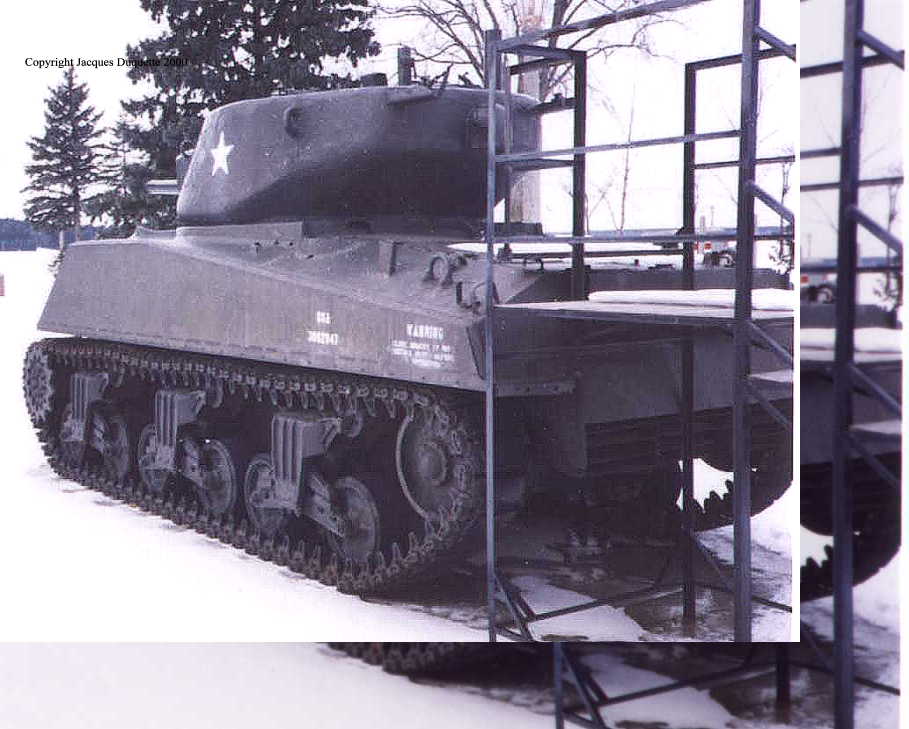

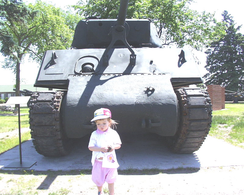
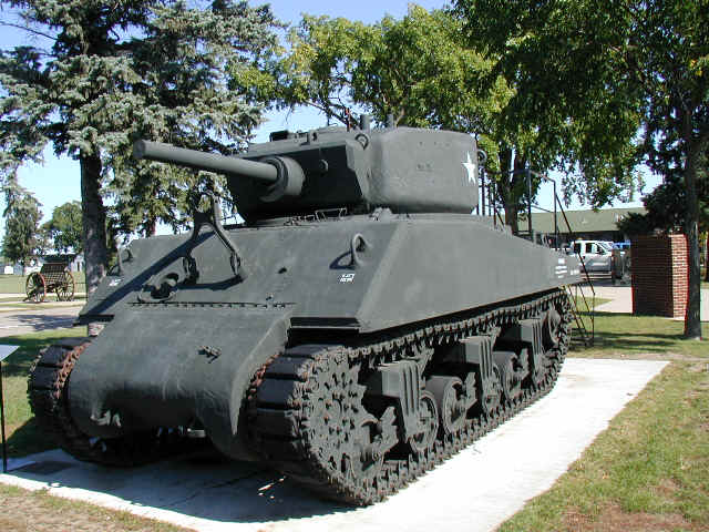
Pictures of the M4A3E2 Jumbo at Camp Ripley, Mn (just outside of Brainerd, Mn) in the Winter of 1995-96. As can be seen, there was a scaffold to allow people to gain access to the rear deck, although you could not walk on the tank itself.
| Purpose Pictures Links |
If you have any questions about my pictures or would like to request additional shots, please email me here.
History of the Camp Ripley M4A3E2 (as I have been told.) The "official" history from the curator of the Camp Ripley Museum is that this Jumbo was part of the Minnesota National Guard, under the 47th Infantry Division, 1/194 armored. The previous history of the tank, such as its history in WWII, is unknown to the museum. Whatever it's WWII history, it served with the MNANG until surplused out in 1959 and stripped of any pieces deemed useful. It was put on the SOUTH impact range as a target for artillery, tanks/APC's, and for artillery direct fire from Observation Point 1. It is not known WHEN this particular tank was put on the impact range or on what part of the impact range it sat. At least one other Jumbo is out on the impact range, but from my observations from OP 1 at a range of about 1200M-1500M, there is VERY little left other than the hull.
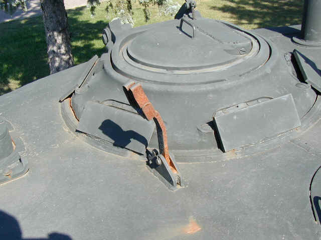
Jumbo #152 was pulled from the range shortly after it was put there when it was discovered how rare a M4A3E2 was. The tank was sent to the Camp Ripley MATES section were the mechanics attempted to repair it to presentable condition. There had been several direct hits on the vehicle, most noticable the large "hole" in the front glacis, just above the transmission housing. This is believed to have come from a direct hit of a 105mm artillery shell from a artillery piece in direct fire model (this account is ONLY speculation and has not/cannot be confirmed). The MATES crew did what they could but this was a side-job and many of the outer fittings had been removed and surplussed out (such as the track holders on the rear plate). Also, the coupola Periscopes had been removed, so plates of steel were welded over the openings. I am not sure what the second large "pipe", located on the right rear corner of the turret roof, is/was for. Since the mount for the .50 cal on the turret is just forward and to the left, I assume it was meant for some other purpose other than a weapons mount.
Pictures of the M4A3E2 Jumbo at Camp Ripley, Mn (just outside of Brainerd, Mn) in the
Winter of 1995-96. As can be seen, there was a scaffold to allow people to gain
access to the rear deck, although you could not walk on the tank itself.

1 2 3 4 5 6 7 8 9 10
The tank was moved and repainted and in its new display area by June of 2000. With the help of a digital camera I was able to get better shots, and without the snow cover, some of the tank is less obscured! :) That is my eldest daughter in the last picture, for scale. She is about 31in tall in the picture.
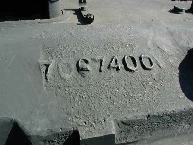
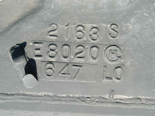
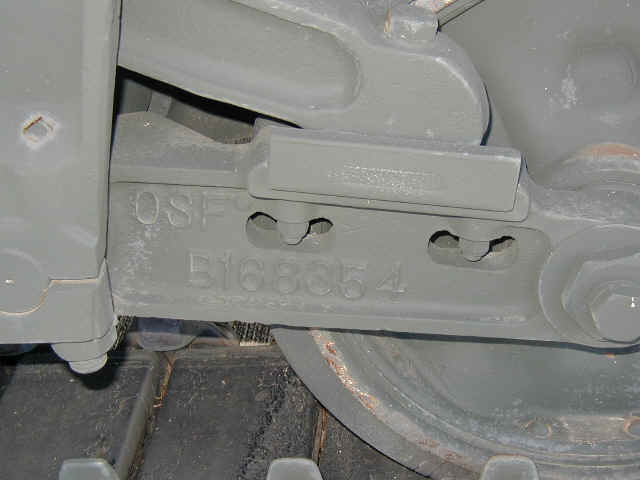
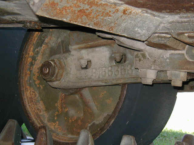
3-8-03 I have strived to get as many serial numbers as possible for a possible ID on who this tank may have been issued to in WWII.
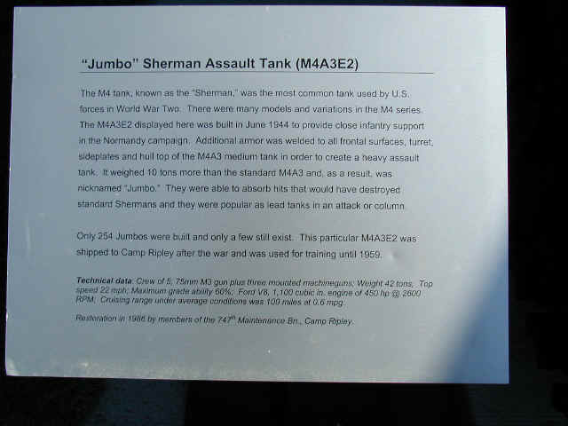
The Plaque next to the Jumbo.

1 2 3 4
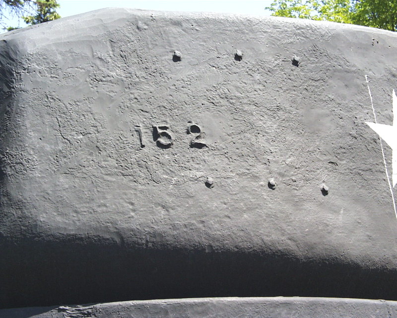
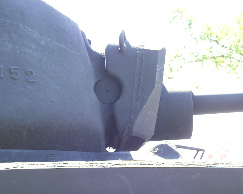
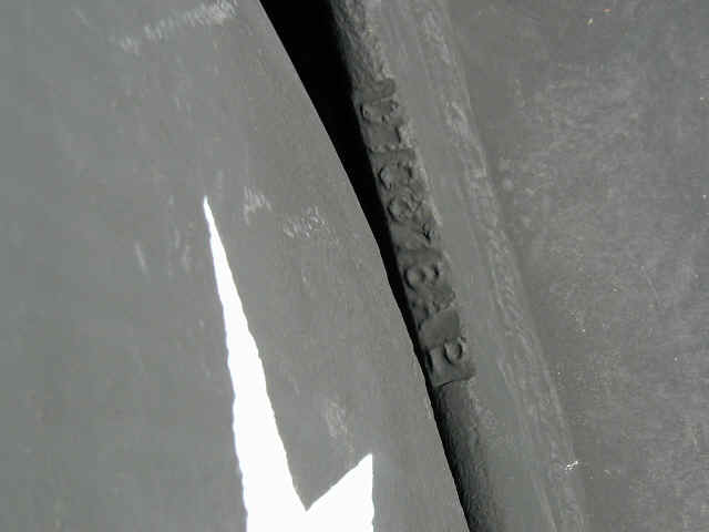
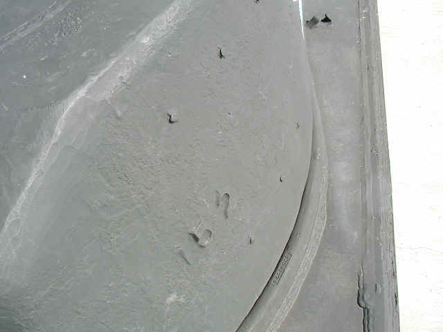
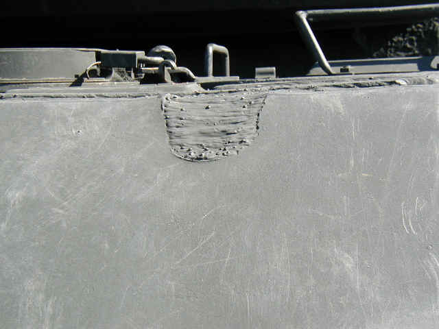
Some of the Serial Numbers. The first is on the left front of the turret, just below the commander's Periscope. 2 & 3 are the hull foundry markings just to the left front of the driver's hatch. 4 is on the hull "lip" around the base of the turret (splash guard?).


1 2 3 4 5 6 7 8 9
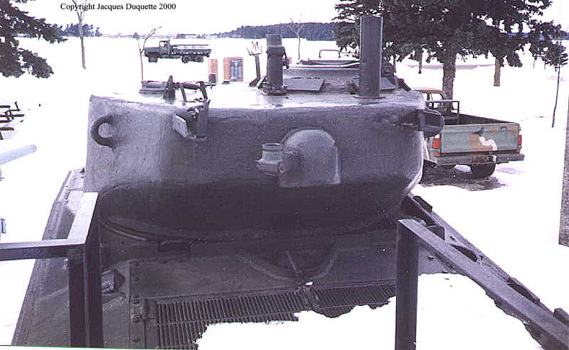
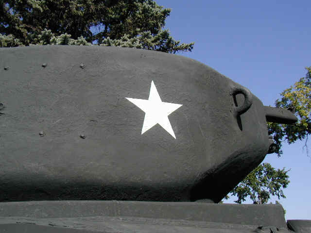
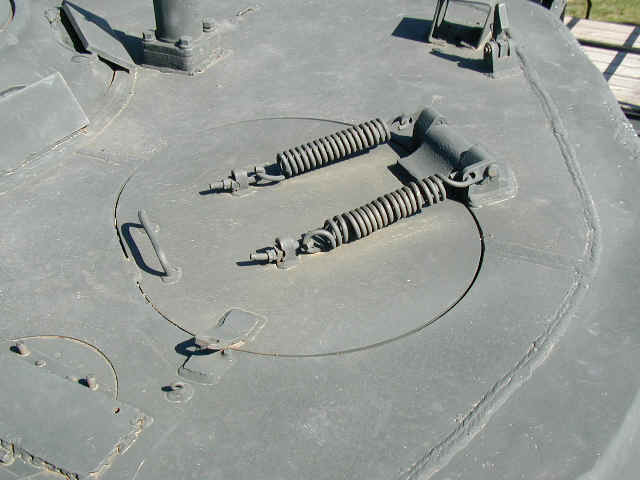
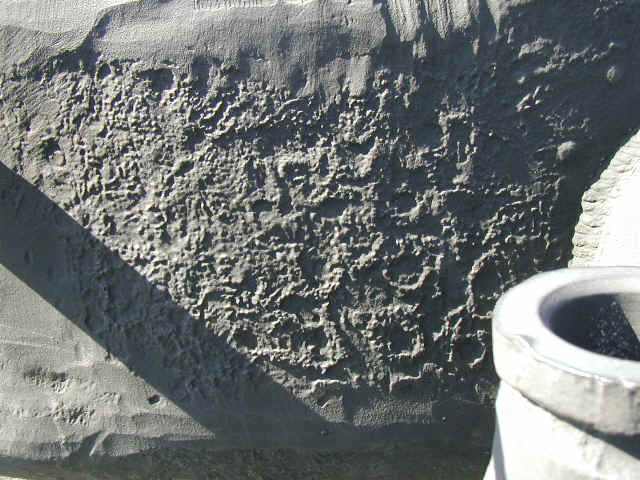
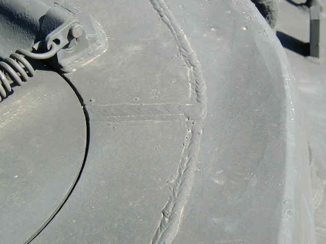
The Turret. Notice the inconsistent casting marks, and the roughly ground away casting seam where the upper and lower turret pieces meet. Also notice the weld lines on the turret top (4,5, & 9), especially around the gunners hatch (5). This will need to be added to the Tank Workshop conversion, I am not sure about the Blast conversion. 7 & 8 show the rough cast texture of the turret. This is caused by the sand that was used in the molds to cast up the turrets being not very tightly packed in the frame. The variability of the packing of the mold sand woudl explain some of the variability in M4A3E2 turret textures. 1 & 2 show how the under-cut is lower than on the Tank Workshop kit, and is "rounder".
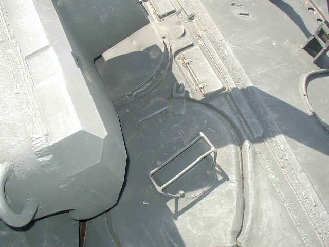

1 2 3 4 5 6 7
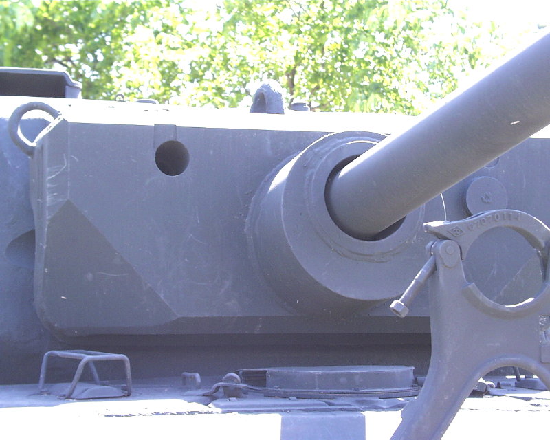
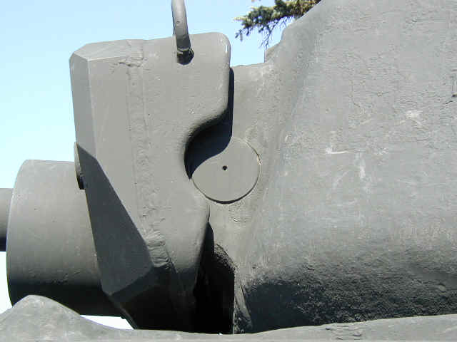
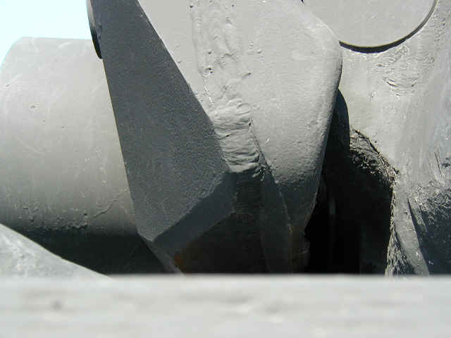
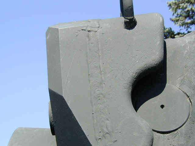
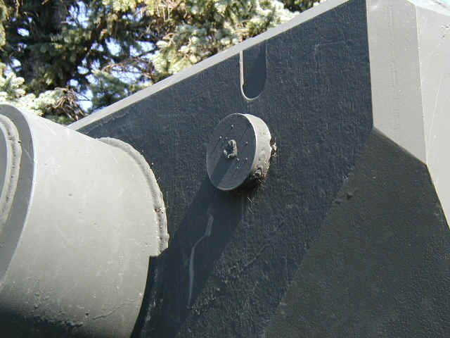
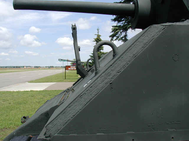
The gun mantlet showing off its distinctive profile and weld detail. The MG port is demilled with a welded on plug to keep out the elements (4). There are some good views of the upper hull top front as well (5 & 6). The gun mantlet on the TW Conversion is positioned at the correct height, in relation to the upper hull, when attached to the turret. The main problem seems to be adding more material to the lower sides of the turret to lower and round off the under-cut. I would think a small "string" of putty, attached at the undercut of the TWS turret bottom, would do the trick.
1 2 3
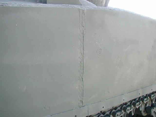
Weld marking for the side of the hull. Notice the distinctive weld-line down the middle of the hull side (2), a feature missing in the Tank Workshop conversion, but easy to replicate.


1 2 3 4 5 6 7 8 9
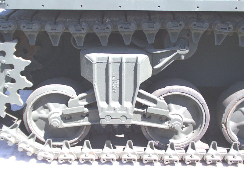
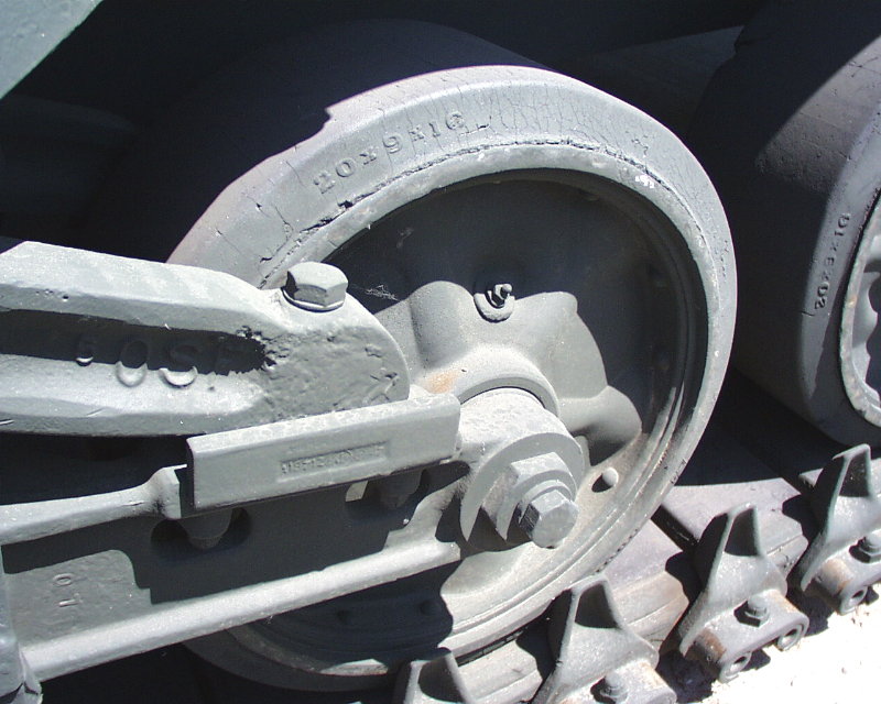
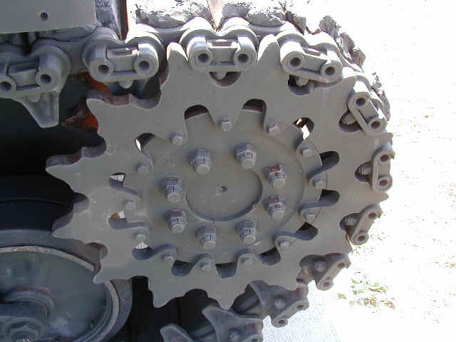
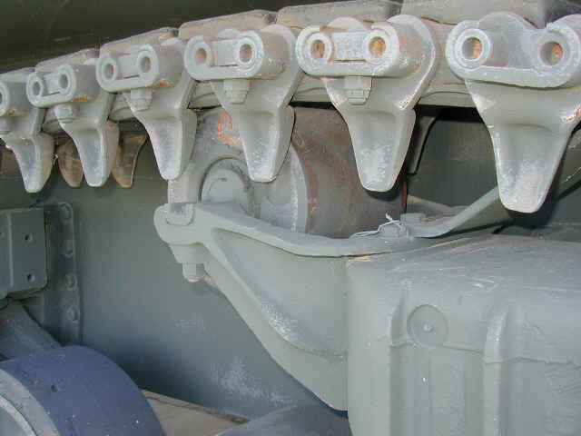
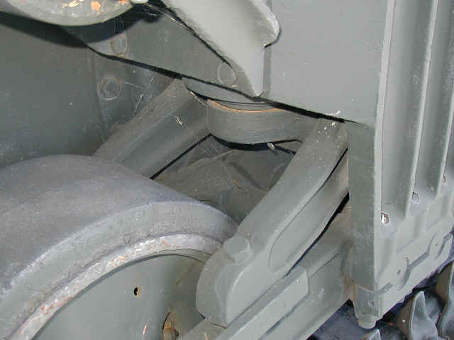
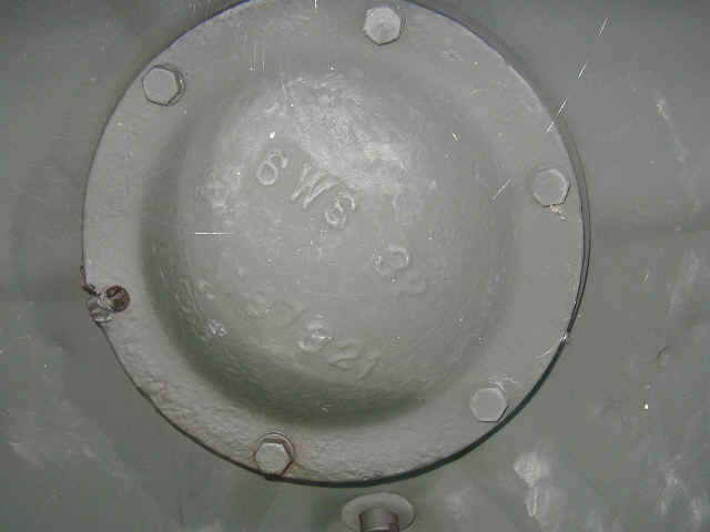
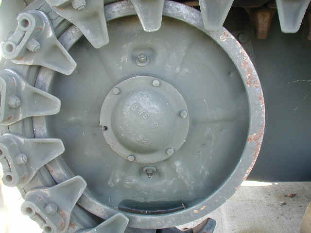
The running gear from the outside, and the track. The track has no grousers, and the museum is not actively looking to replicate or add any, due to budget constraints.
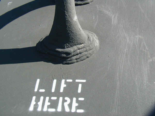
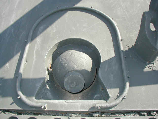
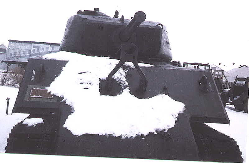
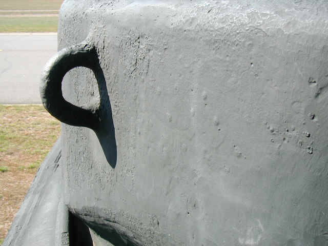
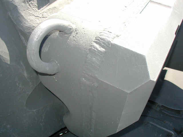
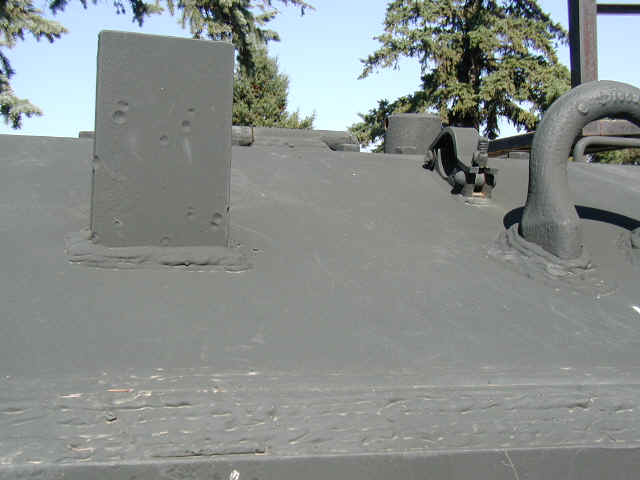
Lift hook and its weld detail. Hull MG and surrounding detail.

1 2 3 4 5 6
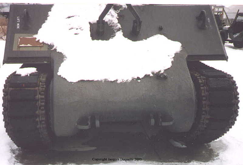
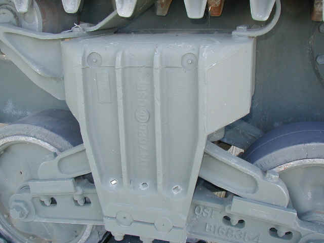
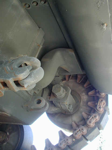
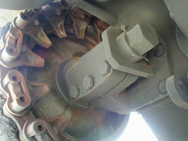
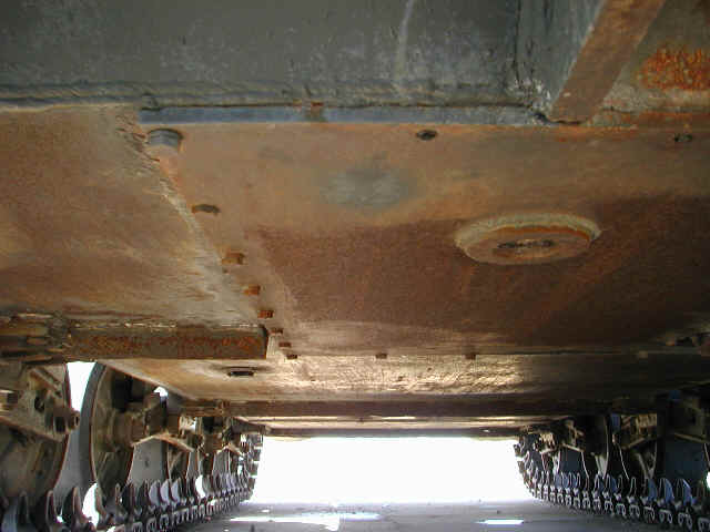
The underside and rear of the Jumbo. Notice the missing track holders on the rear hull plate (6).

1 2 3
4 5 6
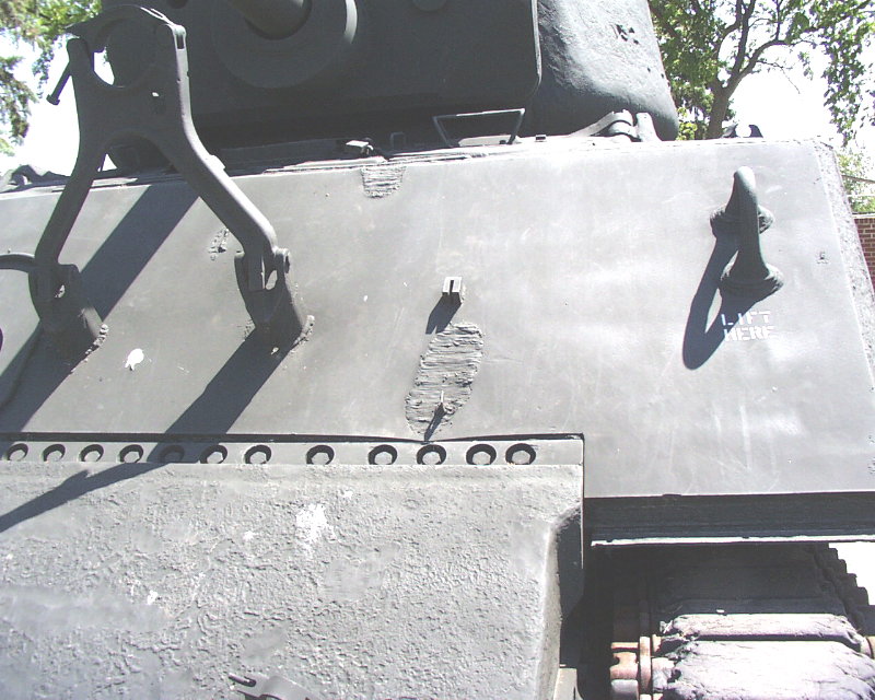
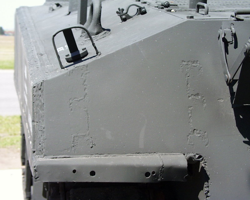
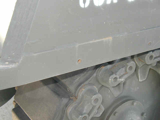
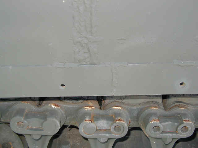
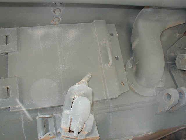
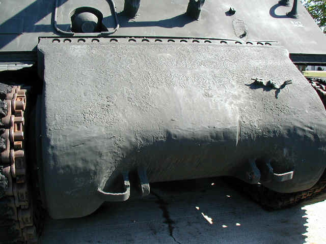
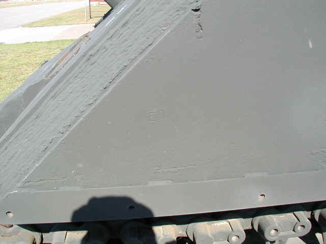
NOTE: the transmission cover thickens after it gets past the mounting bolts strip in a NON-UNIFORM manner (1, 2, & 6). It thickens in two layers, not in one and notice in picture 2 that the transmission housing in the Tank Workshop conversion does not portray this. I am not sure if the BLAST conversion address' this or not. The correction would be a .10 sheet of plastic with a .20 sheet added over the top, and both of these should only go about 1/4 to 3/8 of the way around the front "curve" of the transmission housing, to just above where the towing clevis attachments are. Then, use a spare amount of thin putty to help blend it into the hull (1). In picture 4, notice the rough texture of the front transmission housing. Picture 5 (taken in 2002), and 6 (taken in 2003) show the unique weld details of the front glacis.

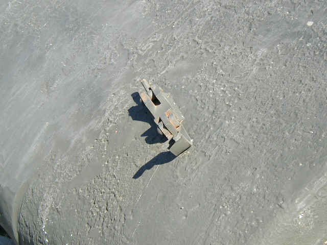
The wounds. Two from supposed 105mm direct hits, the last photo shows some spalling from nearby round detonation.
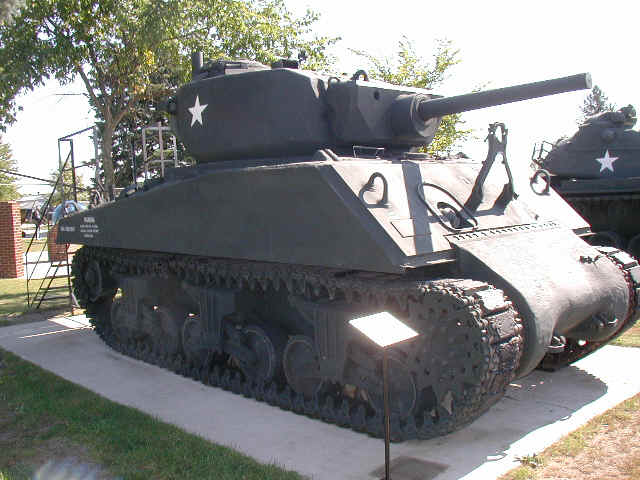
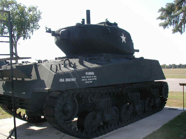
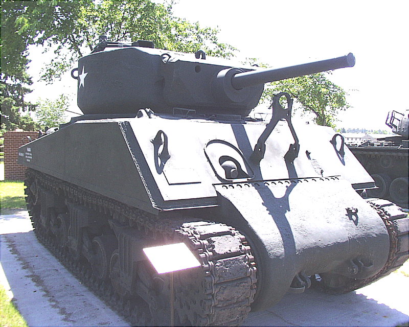
The whole tank.